Section 02 // Acoustic Capture & Front-End Hardware

Recording: Trace the Setup

When producers sample drum kits, upright pianos, guitar cabinets, or found percussion, the physical placement of capsules and the state of preamp switches determine transient snap and phase coherence long before the signal reaches an A/D converter.

Lead Plate REC-200 // Stereo Array Geometry

Read Capsule Angles and Rejection Nulls

A photograph of a microphone stand tells you whether the engineer prioritized mono-compatible coincidence (X/Y, Blumlein, Mid-Side) or time-of-arrival spaciousness (Spaced Pair, ORTF).

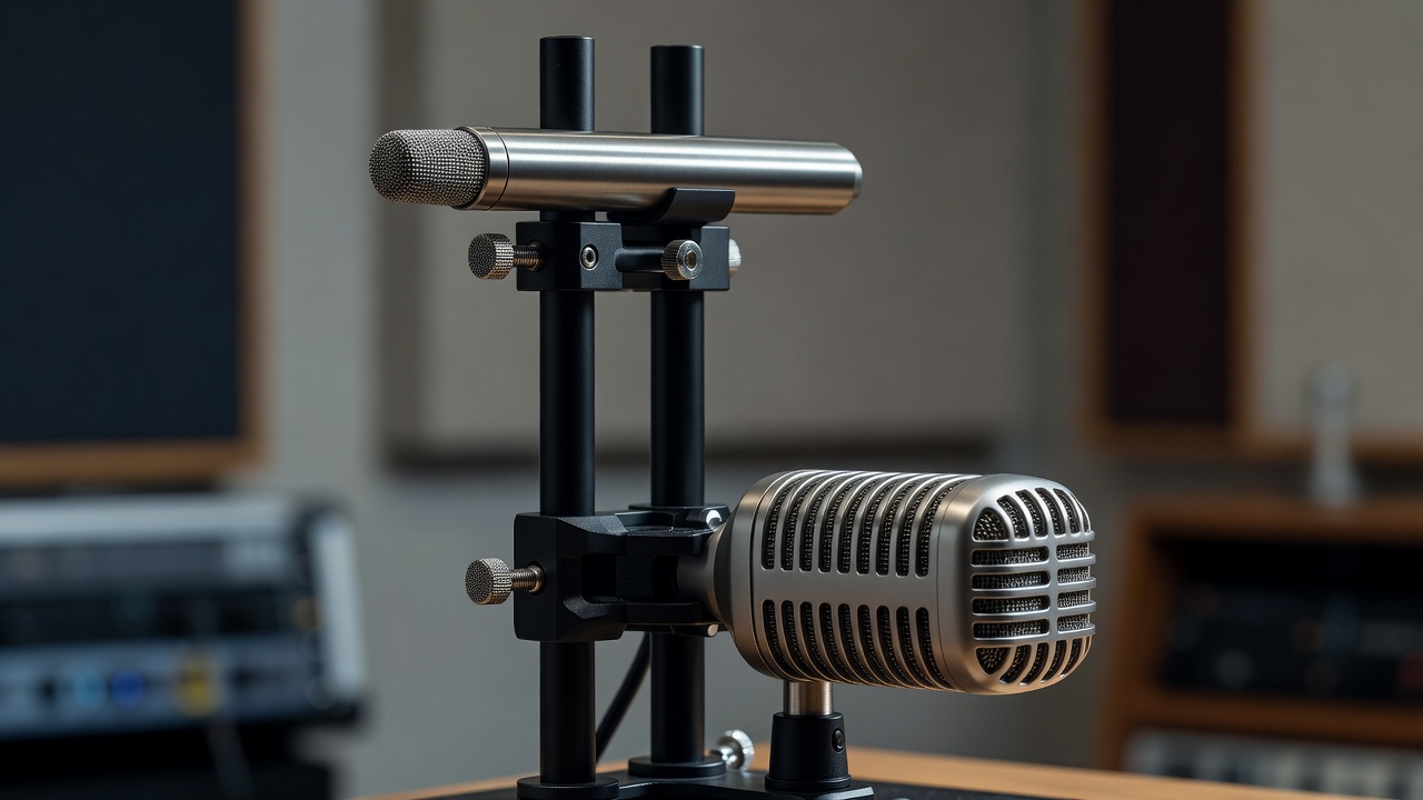
Close-up of a Mid-Side stereo microphone array mounted on a dual vertical clamp with a small-diaphragm cardioid pencil mic aiming forward above a side-address figure-8 ribbon mic
1 End-Address Cardioid "Mid" Capsule 2 Side-Address Figure-8 "Side" Ribbon 3 Coincident Vertical Acoustic Axis 4 Star-Quad Balanced XLR Drop Leads

Catalogue Plate REC-200: Coincident Mid-Side (M/S) Percussion Array

Visual Text Equivalent: Two microphones mounted vertically one directly above the other on a precision anodized stereo bar. The upper microphone is a cylindrical pencil condenser pointing straight ahead toward a drum kit; the lower microphone is a flat-grille ribbon microphone rotated 90 degrees so its front and rear faces point left and right across the room.

What the Image Shows vs. What Equipment Can Do The perpendicular alignment of the two capsules confirms a coincident Mid-Side capture where the Figure-8 null rejects direct center sound. However, the photograph cannot show the Mid-Side matrix decoding (duplicating the Side channel, inverting polarity on the right copy, and panning hard L/R) that must occur on the mixing console or DAW to hear stereo width.
Capsule Geometry
Zero horizontal spacing; capsules aligned vertically within 2cm to eliminate comb filtering
Polar Combination
Cardioid (Mid on-axis) + Bidirectional Figure-8 (Side 90-degree off-axis)
Sampling Benefit
Collapses to 100% phase-accurate mono when the Side fader is pulled down
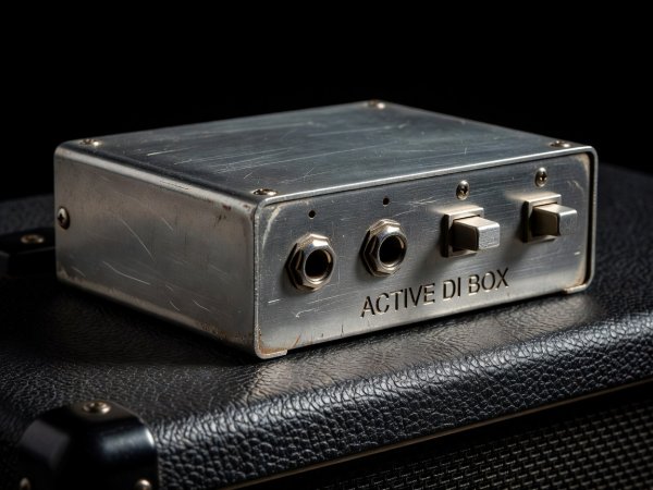
Close-up of a rugged steel direct injection DI box on top of a bass amplifier showing 1/4-inch TS instrument input, thru jack, -15dB pad, and ground lift switch
1 Unbalanced TS Input & Thru 2 Recessed Ground Lift Toggle

Ref. REC-210: Direct Injection (DI) & Re-Amp Interfaces

Visual Text Equivalent: A heavy blue steel DI box resting on a tolex amplifier cabinet. Two black 1/4-inch TS cables occupy the "Input" and "Thru" jacks on the right panel, while a balanced male XLR cable exits the left panel with the "Ground Lift" switch depressed inward.

Recognition Note: When sampling vintage electric pianos (Fender Rhodes, Wurlitzer) or synthesizer line outputs over long studio runs, a DI converts high-impedance unbalanced signals into low-impedance balanced mic-level feeds. Note that an active DI requires +48V phantom power or an internal 9V battery, whereas a passive transformer DI needs no power source.

Impedance Bridge
High-Z (1 Megaohm+) unbalanced TS to Low-Z (150–600 Ohm) balanced XLR
Switch State
Pin-1 shield disconnected via Ground Lift to break 50/60Hz AC hum loops
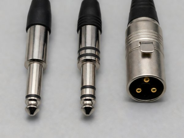
Side-by-side macro comparison of a 1/4-inch TS mono plug with one black insulating ring, a 1/4-inch TRS balanced plug with two rings, and a 3-pin male XLR connector
1 Single-Ring TS (Tip-Sleeve) 2 Dual-Ring TRS (Tip-Ring-Sleeve)

Ref. REC-218: Connector Ring Identification

Visual Text Equivalent: Three machined brass and nickel audio connectors laid across a matte slate surface. The left plug has a single black dielectric band separating tip and sleeve; the middle plug has two black bands creating tip, ring, and sleeve contacts; the right plug shows three recessed silver pins inside a cylindrical shell.

Recognition Note: Counting the insulating bands on an unplugged 1/4-inch jack immediately distinguishes mono unbalanced instrument cords (1 band = TS) from balanced line cords, stereo headphone plugs, or single-jack insert Y-cables (2 bands = TRS).

TS Application
Mono synth outputs, electric guitars, unbalanced pedalboard patching
TRS Ambiguity
A single TRS plug can carry balanced mono (Hot/Cold/Ground), unbalanced stereo (Left/Right/Ground), or console Insert Send/Return

Studio Connector & Polar Pattern Visual Reference

Hardware / Symbol Visual Marker on Chassis Acoustic or Electrical Meaning Photographic Blind Spot
Cardioid Symbol (Heart) Heart-shaped engraving next to capsule toggle switch. Unidirectional pickup; maximum rejection at 180 degrees (rear of mic); exhibits proximity bass boost when close-miked. Internal diaphragm cleanliness or moisture degradation on vintage Mylar capsules.
Figure-8 Symbol (∞) Two touching circles or infinity loop engraved on chassis. Bidirectional pickup; equal sensitivity front and back (opposite polarity); deep 90-degree side rejection nulls. Which face is positive polarity if the mic is mounted upside down without checking badge orientation.
Polarity Invert (Ø) Circle with a diagonal slash illuminated on preamp strip. Flips Pin 2 and Pin 3 (180-degree polarity inversion) to correct phase cancellation on multi-miked drums. Does not fix time-of-arrival delay; only inverts instantaneous voltage polarity.
Bantam TT Jack (4.4mm) Slender brass tip slightly smaller than 1/4-inch, grouped in dense 2x48 rack rows. Professional balanced studio patchbay connection; supports normalled or half-normalled signal splitting. Whether the rear solder lugs or DB25 D-sub harnesses are wired as full-normalled, half-normalled, or non-normalled.