Every electronic instrument communicates its signal flow through panel typography, knob mechanics, and jack groupings. Use these visual plates to distinguish fixed-architecture subtractive synths, FM digital matrices, and 12-bit/16-bit hardware drum samplers.
Lead Plate INS-100 // Panel Flow
Signal Flow Printed on Metal
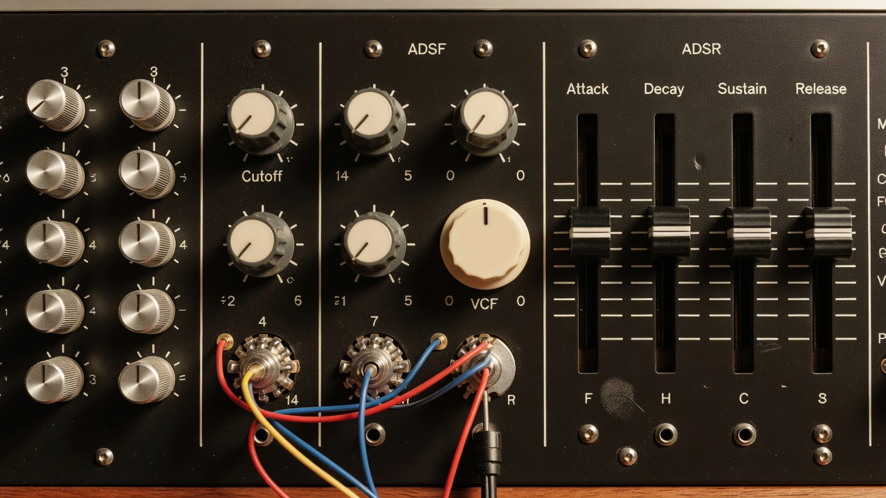
Classic analogue and hybrid synthesizers arrange their front panels left-to-right to mirror audio generation: Pitch and Oscillators on the left, Mixer and Filter in the center, and Envelope Generators plus Master VCA on the right.
1 Detented Footage Switch (32'–2')2 Bipolar Filter EG Mod Pot3 45mm Dust-Sealed Linear Faders4 Unnormalled 3.5mm Patch Bay
Visual Text Equivalent: A black anodized faceplate divided by thin white silkscreen borders into four vertical zones: "Oscillator Bank", "Mixer", "Filter", and "Envelopes". The Oscillator switches have heavy mechanical clicks at 16', 8', and 4'; the Filter section features a central zero-detent knob with negative values to the left and positive values to the right.
What the Image Shows vs. What Equipment Can Do
Silkscreened boxes and indicator lines show the default hardwired signal path when no patch cables are inserted. However, on digitally controlled analogue synths (DCAs) with patch memory, the physical pointer on a potentiometer only reflects the last manual edit—not the active value loaded from a stored preset bank.
Potentiometer Style
270-degree finite-travel conductive plastic pots with painted white indicator lines
Bipolar Controls
Zero-center detent at 12 o'clock allowing positive or inverted envelope modulation
Reference Archetypes
Sequential Prophet-5 panel groupings, Moog Minimoog Model D three-oscillator bank, Roland Juno-106 fader arrays
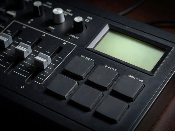
1 8-Channel Pitch/Decay Sliders2 Data Entry Detented Jog Wheel
Ref. INS-112: 12-Bit vs. 16-Bit Sampler Ergonomics
Visual Text Equivalent: Eight vertical sliders with grey caps sits directly above eight numbered trigger buttons (1 through 8), while to the right, a 4x4 grid of square rubber pads sits beside a recessed rotary data wheel and a 2x40 character green LCD display.
Recognition Note: Dedicated vertical sliders per voice (as seen on the E-mu SP-1200) allow immediate tactile pitch-tuning or decay trimming per drum slot. By contrast, a 4x4 pad grid with a large rotary encoder (Akai MPC60 / MPC3000 lineage) prioritizes polyphonic finger drumming and fine start-point scrubbing inside waveform menus.
Control Signature
Dedicated per-voice faders vs. multi-bank velocity pad matrix
Visible Port
3.5-inch Double-Density (DD) floppy drive slot below the palm rest
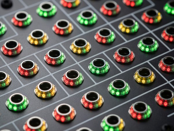
Visual Text Equivalent: A dense 3U Eurorack module faceplate where six 3.5mm jacks along the bottom row sit inside solid white silkscreened rectangles, while upper jacks have plain text labels paired with miniature black plastic trimpots.
Recognition Note: Across almost all modern modular manufacturers, jacks surrounded by a solid colored or white block are signal outputs, whereas jacks without background blocks are control voltage (CV) or audio inputs. Miniature knob-less shafts (trimpots) directly above an input jack almost always scale incoming modulation depth.
Cannot distinguish DC-coupled CV inputs from AC-coupled audio inputs without checking panel legends
Hardware Control Type Comparison
When inspecting studio photography, the mechanical design of a rotary control or switch tells you whether the parameter is directly tied to an analogue circuit or polled by a microcontroller.
Control Element
Visual Identification Cue
What It Confirms
What Remains Hidden
Finite Potentiometer
Painted pointer line on cap; radial scale printed from roughly 7 o'clock to 5 o'clock.
Fixed physical minimum and maximum travel limits.
Whether taper is linear (B-taper) or logarithmic audio (A-taper); whether preset memory overrides physical position.
Endless Rotary Encoder
No pointer line on cap (or surrounded by an LED ring); rotates 360 degrees continuously.
Digital parameter polling; immune to parameter jumps when switching presets.
Exact parameter value unless the companion OLED/LED screen or collar ring is lit and legible.
Linear Slide Fader
Rectangular slot track with horizontal tick marks; common on ADSR envelopes and graphic EQs.
Immediate visual curve recognition across grouped parameters (such as a 4-stage envelope contour).
Whether the fader carries actual audio signal or simply sends 0–5V DC control voltage to a VCA chip.
Mechanical Step Switch
Numbered 1–16 horizontal row of plastic buttons with embedded single or tri-colour LEDs.
X0X-style step sequencing workflow; lit steps show active triggers on the current bar page.
Flam sub-steps, probability percentages, ratcheting, or swing settings applied globally.